
When a Liquid-Cooled Rack Runs Warm: Reading the Loop Before You Blame the CDU
A warm rack is rarely a CDU fault. Read the loop first: flow, filter loading, concentration, particles and air. A field order for diagnosing coolant problems in direct-to-chip cooling.
A rack that runs warm is rarely a CDU fault. It is usually a loop problem the CDU has been quietly compensating for.
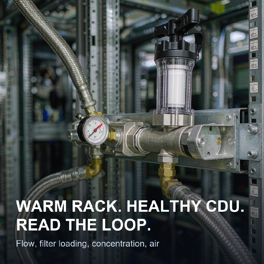
At Glacier Coolant, the calls we take from data halls start the same way. The rack is warm. The CDU says it is fine. Nobody can say which of the two is telling the truth.
Why is my rack delta-T drifting? Drift is flow before it is temperature. A cold plate getting less coolant than it was specified for shows a wider gap between supply and return, and no setpoint change will close it. Check per-node flow against the cold plate maker's number first, then look at the fluid.
What clogs cold plate microchannels? Particles, from three places. Debris left in the loop at install, corrosion products made inside it, and biofilm shed out of warm low-flow pockets. The passages are sub-millimetre. What sails through a strainer will sit in a cold plate.
How often should I sample the coolant? At commissioning, to set your baseline, and then on a calendar. Guidance published by equipment makers puts routine testing at roughly annual, and at roughly six-monthly where the racks carry AI loads. Trend the numbers. Do not file them.
The rest of this piece is the order we work in, and what each reading means.
One hall, two loops, two rule books
Almost every liquid-cooled hall runs two circuits, separated by a heat exchanger inside the CDU. They carry the same heat and follow different rules. Most diagnostic time is wasted by treating them as one system.
| Technology cooling system (TCS) | Facility water system (FWS) | |
|---|---|---|
| What it runs through | Cold plates, rack manifolds, CDU secondary side | Dry coolers, towers, chillers, CDU primary side |
| Typical fluid | Inhibited glycol-water, commonly near 25% glycol | Treated water, site water with a treatment programme |
| Who owns the chemistry | Usually the IT or facilities team, to a tight band | Usually the building team, to a looser band |
| What goes wrong | Particles, inhibitor depletion, biofilm, air | Scale, corrosion, biological control, make-up water quality |
| What you log | Supply and return, flow, filter dP, conductivity, pH | Make-up volume, conductivity, biocide residual |
When a rack runs warm, the question is which loop set the temperature you are looking at. If supply temperature at the CDU is on target and the rack is still hot, the problem is downstream of the heat exchanger, and that is TCS territory. If supply itself has drifted, start on the facility side and work inwards.
Start with the numbers you already log
You are probably collecting most of what you need. The discipline is reading them together instead of one at a time.
Five are worth pulling before anyone opens a valve:
Supply and return temperature, per rack or per manifold
Flow, per node where the design gives you a target
Filter differential pressure, and how fast it climbs
Pump power draw at a fixed speed
Make-up water additions, which is the number nobody logs and the one that explains the most
A loop that needs topping up is telling you something. Either it is leaking, or it is being diluted, or someone has been adding water instead of coolant.
| What you see | Most likely cause | How to confirm |
|---|---|---|
| Return temperature rising, flow steady | Fouling on the heat transfer surface: film, deposit or biofilm | Compare delta-T against commissioning data at the same load |
| Flow falling at constant pump speed | Restriction at the filter, strainer or plate | Filter dP rising means the filter; dP steady means look downstream |
| Both drifting slowly over months | Chemistry drift: concentration, inhibitor, pH | Refractometer, pH, inhibitor residual |
| Step change right after maintenance | Air in the loop, or a top-up with the wrong fluid | Bleed the high points, then check concentration |
| One rack hot, neighbours normal | Flow balancing, not chemistry | Re-measure flow per node against the cold plate spec |
The three failure modes that fill a service log
In our own industrial service record, sorted by root cause across 119 callouts, performance complaints were 45%, corrosion 23%, blockage 18%, and other operating faults 14%. Those are process and cold-storage loops, not data halls, so do not read them as a data-centre distribution. The three mechanisms are the same ones, and they map like this: the full industrial breakdown sits in how 119 field failures sort by cause.
| Failure mode | What it looks like from the aisle | What drives it | What holds it back |
|---|---|---|---|
| Particles and blockage | Rising delta-T, rising filter dP, one rack worse than its neighbours | Install debris, corrosion products, inhibitor sludge, biofilm | Staged filtration to the cold plate maker's target, and a flush before first fill |
| Corrosion and inhibitor depletion | Discoloured fluid, rising conductivity, metal in the filter | Oxygen entry, mixed metals, inhibitor consumed by heat and time | Oxygen exclusion, a grade matched to the metal list, inhibitor on a test schedule |
| Biological growth | Warm spots that do not respond to flow, slime in sample bottles | Dead legs, low-flow pockets, diluted glycol, warm return | Commissioning discipline, biocide regime, keeping concentration in band |
They feed each other. Corrosion makes particles. Particles make a low-flow spot. A low-flow spot makes a home for biofilm. Most loops that end up in trouble have all three running by the time anyone samples.
Particles: where they come from
Two sources, and they need different responses.
Install debris is the one you can control and the one people underestimate. Machining swarf from the cold plate bodies, plastic from manifold components, thread sealant, general assembly grit. If the loop was not flushed to a defined cleanliness target before first fill, it started its service life dirty. Published commissioning guidance from the Open Compute Project points to staged filtration finishing at roughly 5 microns, with flushing at about 3 to 5 ft/s to move sediment. The cold plate manufacturer's number governs, not the guideline.
Operational debris arrives later. Corrosion sheds oxide particles. An inhibitor package that has been overheated, diluted wrong, or mixed with an incompatible one can drop sludge. Biofilm sheds. Seals and elastomers shed. Polymer tubing and liners release small-molecule extractables that show up as a slow pH drift, a creeping conductivity, or a deposit that does not match any corrosion chemistry you would predict.
One diagnostic habit pays for itself: when a filter comes out early, look at what is in it. A filter loading faster than the schedule expected is not a filter problem. It is evidence that the source is still there.
Concentration, pH and the inhibitor you cannot see
Glycol concentration is the reading most often guessed and most easily measured. Use a refractometer calibrated for the coolant, not a floating-ball gauge, and check it at fill and at every service visit.
Published references put a PG25-class fluid at roughly 24.5 to 29.5 volume percent glycol, with pH somewhere in the 8.0 to 10.5 range depending on the inhibitor technology. Some named products run a narrower pH band than that. Those figures belong to specific guidelines and specific products, and they are not universal alarm limits for your loop. Your baseline is the number you recorded at commissioning, and your trend is the thing that matters.
Where the metal list itself is the suspect — copper tube feeding an aluminium manifold, a brazed joint between them — the mechanism is set by the metals, not by the fluid. That is why mixed metals decide the corrosion rate long before any additive does.
Two ways to break a loop with a hose:
Topping up with plain water drops the glycol fraction and dilutes the inhibitor package at the same time. You lose freeze margin and corrosion protection in one move, and the conductivity reading will look better while the loop gets worse.
Topping up with a different glycol changes the inhibitor chemistry. Two packages that are each stable alone can drop solids together. If you do not know what is in the loop, sample before you add anything to it.
Our own filling instructions give a pH band of 7.5 to 11 for general service, narrowing to 7.5 to 9.5 where aluminium sits in the wetted list. Aluminium is the metal that suffers when pH climbs, which is the opposite of the habit most crews bring from steel systems. Where a loop has been dosed to correct pH without checking that list, the correction is often the cause.
Inhibitor depletes. It is consumed by heat, by oxygen, and by time, and a loop running warm supply temperatures with heavy thermal cycling eats it faster than a loop that sits at a steady temperature. Concentration and pH are the cheap proxies. Inhibitor residual is the real number, and it belongs on the annual test.
Biology: dead legs and warm pockets
A glycol loop held in spec is a poor home for microbes. A glycol loop that has drifted out of spec is a better one than most people expect, because diluted glycol at warm temperatures is a carbon source.
The places that grow things are the places that do not move: bypass lines that are never exercised, spare CDU circuits standing full, the top of a manifold, the far end of a branch nobody balanced. Biofilm is both an insulator and a restriction. It cuts heat transfer exactly where the channel is least forgiving, and once it is established it resists almost everything you can do from outside the rack.
Prevention is commissioning. Flush with water that meets a conductivity and microbiological spec. Do not leave a flushed loop standing wet for a week before filling it. If a loop has to stand, stand it dry or stand it inhibited.
Air where it does not belong
Air is the failure mode that surprises people, because it does not look like chemistry.
One data centre in northern China lost a pump casing to cavitation because there was no air release point on the pump discharge. The entrained air came out where the pressure dropped, and it took metal with it. On another site, foaming at the pump was cured with an antifoam dose; left alone, foam had been causing the same cavitation damage and hammering the pipework.
Both cases are the same lesson. Air in a loop is oxygen in a loop, and oxygen drives corrosion while the bubbles themselves destroy pumps. Vents at high points, a working air release at the pump discharge, an expansion tank that is properly water-sealed, and a return line that does not cascade into the tank and drag air down with it. Four details, none of them expensive, all of them cheaper than a pump.
A sampling rhythm that costs less than one cold plate
A cold plate is worth more than a year of testing. Here is the schedule we recommend to operators, with the public guidance on testing frequency folded in.
| When | What to test | Why this one |
|---|---|---|
| Before first fill | Conductivity and microbiological count on the procedure water | You cannot commission clean with dirty water |
| At commissioning | Concentration, pH, conductivity, inhibitor residual, appearance, particle count | This is your baseline. Without it every later number is an opinion |
| First 90 days | Monthly: concentration, pH, appearance | New loops move. Catch the move while it is still a trend |
| Steady state, AI density | About six-monthly | Published equipment guidance for high-density loads |
| Steady state, general | About annual | Published equipment guidance for routine service |
| After any top-up or maintenance | Concentration and pH | Half of all chemistry problems start at a top-up |
| Every filter change | What is in the filter, logged and photographed | The debris tells you which failure mode you are in |
Log it on one timeline with your maintenance events. A pH change that lines up with a top-up is a different story from the same change with no event next to it.
What we settle before we call a loop healthy
Send us a sample and here is what comes back.
A reading against your baseline, not against a textbook. Concentration, pH, conductivity, appearance, and particle load, each against the numbers your loop recorded at commissioning.
A material check. We match the grade to the metals and elastomers actually in your wetted list. Aluminium in the list changes the grade, and the grade number is where that shows up: an L suffix on our grades means the inhibitor package was built for aluminium. The grades supplied for direct-to-chip loops are listed by temperature band and conductivity.
A refill discipline. What to top up with, what to top up to, and how to record it. Most loops that drift do so at the top-up, not in service.
A closed loop on the problem itself. Ask, check, test, change, follow up. If the fix does not hold, we go back to the first step rather than dosing something else and hoping.
Eight things you can settle yourself this week
Pull the commissioning baseline out of the handover pack. If it does not exist, create one now.
Check glycol concentration with a calibrated refractometer at the furthest sample point.
Log filter differential pressure weekly for a month. The slope matters more than the value.
Walk the loop for dead legs and unvented high points. Photograph them.
Confirm what is in the make-up water, and who is allowed to add it.
Compare per-node flow against the cold plate specification on the hottest rack.
Check the expansion tank seal and the pump discharge air release.
Write down the date of the last top-up, what went in, and how much.
None of that needs a supplier. All of it changes what a supplier can tell you from a bottle.
Final thoughts
The CDU is the most instrumented thing in the hall and the least likely to be the problem. It will hold a setpoint while a plate fouls, while concentration slides, and while a dead leg grows a film, and it will tell you it is fine until the day it cannot.
Read the loop instead. Flow, filter loading, concentration, and air. Those four account for most of what arrives as a hot rack, and three of them cost nothing to check.
If you are still writing the specification rather than fixing a running hall, start with what belongs in a direct-to-chip coolant spec. If you are converting an air-cooled hall, what changes in the loop during a retrofit is the companion piece.
Glacier Coolant has spent three decades on circulating loops that run colder, dirtier and harder than a data hall does, and the failure modes have not changed. What has changed is the size of the channel at the end of the loop.